
One of the three project boats the Marine Systems students are working on during the second semester is a little out of the ordinary for The Landing School. Traditionally, the sail and powerboats we bring in for the winter, for everything from re-wiring to re-powering, are recreational vessels. This year we have a 25’ BHM lobsterboat….not a pleasure craft like the Sisu 30’ we are also working on, but a real commercial boat. While the fundamentals of the systems are the same, there are enough differences to make it really interesting. For starters the customer has a different perspective on what’s important and that in its self is a great lesson for the students – listen to the customer.
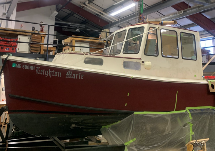
There is a lot happening on a small boat and with that come challenges. The existing GM 292 straight 6 gasoline engine, delivering 150 HP and weighing 700lbs, will be replaced by an Isuzu Turbo Diesel model 6BG1. When the replacement is not the same as the original, inevitably there are fit issues. Last year the engine beds had to be cut down, in situ, and reconfigured for a new engine in both the Bristal and Pearson sailboats we re-powered. This year there is an added complication. One would think more horsepower (226hp) would mean better performance, but the boat runs nose down and ideally the center of gravity should be further aft…which will not be helped with the new engine weighing more (1,100 lb). Ideally, we could get the bow up by moving the engine aft. However one wouldn’t want to keep the engine at the same level, as this would mean the propeller angle needed to change and in a direction that would cause the nose to drop!
The Yacht Design program was called in to run the numbers on the effects on trim of relocating the engine and to consider the options regarding shaft angle. Analysis on a boat standing there in front of you is a little different than manipulating 3D models. Measurements and calculations of the “as built” are required. It was determined that the engine needed to move aft…and move down into the keel. How far it could be lowered was uncertain, but it was clear it was going to be a tight fit.

There were a couple of bottom girders which would no longer be suitable on which to mount the engine, but couldn’t easily be removed. However they were “structurally compromised” and couldn’t be relied on to support the new engine in its new location. Reinforcing them adequately, in-situ, would be a messy fiberglass job, on top of dirty, dubious existing laminate. Any new structure would constrain the available space for the engine lowering exercise. Marine Systems enlisted the Composites Boatbuilding class, who happened to have some thin (1/4”) prepreg carbon plate, intended for high temperature tooling. After taking templates off the side of the as built girders, a doubler was cut from the carbon, to match the geometry of the girder. This was bonded with Gougeon G-Flex epoxy onto the inside of the existing girders, only minimally reducing the space available for the engine. This ¼” plate, on its own, is stronger and stiffer than the 1” wide ply girder encapsulated with ¼” of fiberglass and bonded to the hull shell.

It was still going to be a tough call as to where the engine mounts could be located, such that the engine could fit without actually getting the engine in there. Again no accurate 3D model of either the bilge or the engine was available, so a more practical approach was necessary. A fiberglass “shell” was molded around the sump and lower regions of the engine, defining the extent including fittings and lines. This was light, and easy to handle, and soon proved exactly where the engine could (and could not) be positioned.

The location of the engine mounts now defined, the structure to which these would be bolted could be fabricated and attached to the inboard side of the carbon-reinforced girders.
The next challenge was to get the engine up off the shop floor and into the bilge. A slot (to be repaired later) had been cut in the cabin top, but not through the aft region as this would have destroyed the shape integrity. This meant the pick point had to be swapped just aft of the cabin, without setting it down, as the cockpit sole would likely not have supported the weight of the engine, with chain blocks rung through the cabin top slot, and moved forward.

Of course getting the engine into the boat is only one part of the re-power process. There is still a lot to do (replacing the shaft and propeller, replacing hydraulic pumps and plumbing for the pot hauler and steering, new rudder and tiller linkage, new batteries, battery box and cables, new dry exhaust stack) and the task list is updated regularly.

Underneath a new cutlass bearing, PSS dripless shaft seal and stern tube is being fitted at a slightly different angle. Of concern is getting cooling water to the shaft seal. The engine has a dry exhaust and no raw water flow to inject into the seal. A forward facing scoop is going to serve this function.
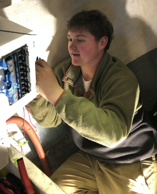
Rewiring is underway.
And then there will be the repair of the cabin top, some fresh paint, and putting it all back together “like new”.
